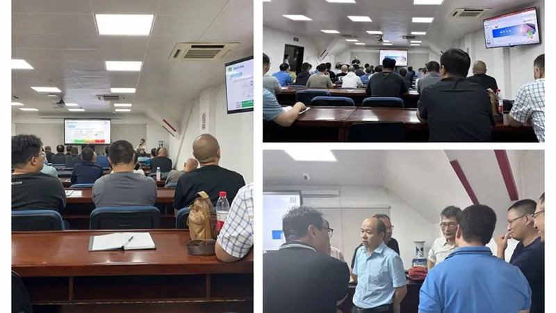
Welcome to Shanghai huijue network communication equipment Co., Ltd

Athermal Arrayed Waveguide Grating Module Introduction

The athermal arrayed waveguide grating (AAWG) module uses mechanical compensation to reduce the influence of wavelength drift caused by chip temperature changes, does not require additional power supply, and has high stability and reliability. From a structural point of view, the main body of the AAWG module is composed of six parts: single-channel input FA, chip, multi-channel output FA, compensation base, compensation rod, locking knob, and packaging shell. See Figure (1) and Figure (2) for details. .


Figure (1) AAWG main structure Figure (2) AAWG module package structure

working principle

The chip is the core of arrayed waveguide grating function realization, and its structure mainly includes the following five parts, as shown in Figure (3).

(1) Input waveguides (input waveguides): receive external wavelength signals;

(2) Input star coupler (star coupler): also called slab waveguide, which couples the wavelength signal to the array waveguide;

(3) Arrayed waveguides (grating waveguides): wavelength signal transmission, the length of the waveguide increases sequentially by ΔL, and a fixed optical path difference is generated for the passing optical signal, which is equivalent to the grating effect;

(4) Output star coupler (star coupler): also known as slab waveguide, which focuses the diffracted wavelength signal into the output waveguide (interference principle, similar to Young’s double-hole interference);

(5) Output waveguides (output waveguides): distribute and output signals of different wavelengths to the receiving end.


Figure (3) AAWG chip structure

The working principle of the AAWG chip is shown in Figure (4): When a beam of light containing multiple wavelengths propagates through the input waveguide and enters the focusing plate, the beam is approximately unlimited laterally, and the beam is diffracted in the focusing plate area. When entering the input aperture of the arrayed waveguide, the light beam is coupled into the arrayed waveguide. In order to reduce the coupling loss, a tapered transition waveguide design is often used at the input and output apertures of the arrayed waveguide. According to the structure of the slab waveguide region, when the light input from the central input waveguide reaches the input aperture of the arrayed waveguide, the optical paths experienced by it are equal, so the phases of the light beams coupled into the arrayed waveguide are also approximately equal.

When each light beam is transmitted to the output aperture of the array waveguide, since each adjacent waveguide of the array waveguide has a certain equal length difference, the light beams of adjacent output apertures have a certain phase difference. The beams of each output aperture undergo multi-beam diffraction and interference in the area of ​​the second slab waveguide, and the position with the highest light intensity is always located at the center of the arc at the output end of the Rowland circle, and the order of interference depends on the length difference of the array waveguide. Due to the dispersion properties of light, light beams of different wavelengths under the same interference order will be focused on different positions in the second focusing plate area, and the receiving waveguide can be placed at the appropriate position of the Rowland circle to obtain the spatial separation of different wavelength channels.


Figure (4) AAWG chip working principle

Temperature Compensation Scheme

Temperature characteristic compensation is the key to realize the function of arrayed waveguide grating.

Arrayed waveguide grating grating equation: nsdsinqi+ncDL+nsdsinqo=ml, where sinqi=xi/Lf, sinq0=x0/Lf, Lf is the length of the slab waveguide, xi and xo are the distances between the input waveguide and output waveguide and the center input waveguide and center output waveguide respectively . ns and nc are the effective refractive indices of the slab waveguide and the arrayed waveguide respectively, d is the distance between the arrayed waveguides, DL is the optical path difference between adjacent arrayed waveguides, and m is the diffraction order of .

The athermal arrayed waveguide grating chip material silicon dioxide has a high thermo-optic coefficient, and its refractive index will change with the temperature. The output wavelength has a linear relationship with the temperature change, and the wavelength change rate with temperature is about 11pm/°C. Find relevant information on the derivation results of the array waveguide equation:


In order to reduce the influence of temperature on the wavelength drift of the arrayed waveguide chip, the implementation process of temperature characteristic compensation of our AAWG products is as follows: cut the slit at the input plate waveguide position of the chip, so that the chip is divided into two parts (the first part contains the input waveguide part and the input plate waveguide, the second part contains part of the input slab waveguide, the array waveguide, the output slab waveguide, and the output waveguide). At present, in the process realization, our company adopts the compensation base and the compensation rod of special material and expansion coefficient to realize the relatively small movement of the two parts of the chip to be cut, so as to achieve the temperature characteristic compensation of the product, as shown in Figure (5).

(1) By adjusting the 1/2/3/4 knobs, the two parts are displaced along the cutting line, so as to accurately calibrate the AAWG output wavelength.

(2) Due to the difference between the thermal expansion coefficient of the compensation base and the compensation rod and the thermal expansion coefficient of the chip, displacement complementation is realized to achieve temperature characteristic compensation.


Figure (5) AAWG temperature characteristic compensation method

Compensation Verification Results

The verification results of our athermal arrayed waveguide grating module are shown in Figure (6). The actual curve is the result of our product sampling test.

(1) In the range of -10 to 65°C, the wavelength drift meets ±0.05nm;

(2) In the range of -10~85℃, the wavelength drift requirement is ±0.05nm, which can be customized.


Figure (6) Relationship between wavelength shift and temperature

Various types of AAWG such as 50G/100G have the characteristics of low loss and polarization dependent loss, low crosstalk and so on.